- SolidWorks Propeller for SolidWorks World 2015
I attended SWW2015 in Phoenix AZ as a member of the FabLab
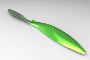
display. Prior to the users group meeting, I downloaded a propeller created in SolidWorks and prepared it for machining on a ShopBot CNC machine.
Before I started, I reviewed two training videos on the ShopBot website for two sided machining created by TJ Christiansen:
a shorter one that shows the machining and registration in process and a long one that is a detailed review of how to prepare and machine a 3D file such as an .stl using Cut3D and VCarve Pro.
I chose Aspire as my CAD/CAM software since I could bring in the 3D component and create the registration or indexing holes and hold downs
in the same software.
I created 3 different files that were inter-related. In the first file, I set up a
base board that could be screwed onto the table to help me register my machining board. In this file, I set:
- The
size of the base board and the machining board: 20 inches tall and 9 inches wide
- The thickness of the material:
.75 inches thick
- The origin of the X and Y axes: In the center of the material
- The origin of the Z axis: At
the table rather than the top of the material
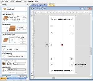
Once the virtual representation of the material appeared, I used the Vector drawing tools on the CAD side of
the Aspire software to draw 4 registration or indexing holes the size of the dowels (plus a .01 allowance). Be sure to
align all the holes so that they are evenly spaced, then center the group of holes in the virtual material. The
align and centering tools are found under the Transform section of the CAD side.
I also drew where to screw down
the base board and the machining boards.
I then saved this file as the Base file, then Saved As: Side 1 to bring
in the 3D component and prepare it for machining.
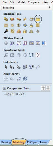
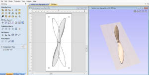
To bring in a 3D model or
component, click on the Modeling tab at the bottom of the CAD screen. The Import 3D component is in the upper right corner
of the menu screen.
Since SolidWorks parts are drawn in a different orientation than is normal for CNC machining, the part will have
to be rotated. You can also resize the model for the size material you have available.
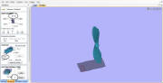
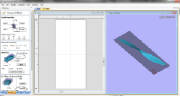
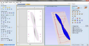
Once the component was imported, I made sure it was centered in the virtual material. (You can open both
the 2D and 3D views at the same time with the correct icon.) I then had Aspire create Vectors around the 3D component.
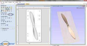
Toolpathing the file is a combination of 2D tool paths (pocketing the registration or indexing holes, drilling
the marks for where to put the hold down screws, profiling on the line for the center lines of the base board) and 3D toolpaths
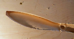
(roughing the propeller along the grain of the wood with a quarter inch ball-nose bit, finishing the 3D file with the same
bit, but with an 8 or 10 % stepover to get a smooth finish)...and then back to 2D profile outside with tabs to cut out the
propeller.
I then saved Side 1, and did a SaveAs for Side 2.
On the new Aspire file, I mirrored the registration
holes, and the vector surrounding the propeller to be sure I had the right orientation when I imported the .stl again, this
time from the opposite side. No need to re-toolpath the hold downs, They will be obvious from holding down the first side.
Review the shorter video for helpful hints on how to set up the files for machining. My files are a little
different, but the idea is the same.
Preparing the Base Board-Put down the base
board on the table in the same orientation as the CAD/CAM file
-Find the center of the board (drawing diagonals across
the top helps)
-Zero the X and Y in where the diagonals cross (Z2 or use the button on the Keypad Screen)
-Zero
the Z at the table surface
-Mark the Base hold downs and screw the board down
-Machine the center lines on
the Base board
-Pocket the Registration/Indexing holes in the Base board
-If you have not done so, chuck the quarter
inch ball nose bit in the spindle/router
-Re-zero the Z at the top of the Base board...this will be the new "table"
after you put down the Machining board
P
reparing and Machining Side 1-Center the Machining
board on the Base board as best you can
-Mark the Machining hold downs and screw the board to the Base
-Run the
Registration/Indexing holes on Side 1 of the Machining board
-Run the Roughing and Final passes of the 3D files
Flipping the Machining board
-Unscrew the Machining board and flip it the correct way!
-Insert
dowels into Registration/Indexing holes to position the Machining board. NOTE: be sure the dowels are long enough to
get the board in the correct location, but not so long that the Machining board does not sit flat on the Base board
-Screw
down the Machining board.
-Run the Side 2 Roughing and Finishing passes
-If necessary, cut out the finished
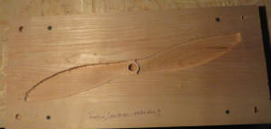
propeller
The finished propeller (still in its substrate) aligned perfectly as an example for the SWW2105.